Where Professor Muller screwed up...
Go to Lecture 4 - Gravity and Satellites II, between 51:00-53:00 into the lecture...
While explaining the concept of a jet engine, Professor Muller drew a small propeller on the front of the jet engine and wrote the word TURBOPROP on the blackboard. He explained that the propeller is used to make the jet engine more efficient as it flies. Unfortunately, he drew the engine cowling so that it encased the small propeller. This is not a turboprop engine but in fact a turbofan engine. The idea of a turbofan is to provide a bit of additional thrust by having the turbine shaft drive the larger diameter fan in front of the turbojet section of the engine to provide a "shroud" of cool air around the hot exhaust gases emitted from the engine. This is called a bypass engine because the jacket of cooler air "bypasses" the hot section of the engine. The ratio of bypass air to hot section air is used to describe the general efficiency of the engine. A "high-bypass ratio" turbofan engine provides an equivalent amount of thrust with greater fuel efficiency than the pure "turbojet", or low bypass-ratio engine. Turbojet engines (indeed, the original jet engines) tend to be gas hogs and produce a lot more noise than their turbofan counterparts.
The turboprop is yet another beast entirely. These engines use "jet" engines to produce some thrust, but to also provide torque to turn a large external propeller attached to the front of the engine. Because of the extreme difference in the RPM of the jet portion of the engine (on the order of 30,000 RPM at cruise, for example) and the RPM of the propeller out front (typically 2000 RPM at cruise, typically), the two are coupled either with either mechanical gears or gas that tends to be smoother, quieter, and more reliable than the mechanically-coupled engine and propeller .
Below are some examples of each type of engine/propeller combination so you can tell the difference next time you're looking at an aircraft engine:
This photo is of a Boeing 707, one of the earliest commercial passenger jets that used turbojet engines. Notice the cowling is long and streamlined and has a continuous curvature along its length. This is so that nearly all of the air that enters the inlet is passed through the hot-section of the engine and is heated and blown out the back to produce thrust. Think of this as a "near-zero" bypass ratio engine.
The photo of the Boeing 707 engine above shows a small bypass nozzle on the engine, but it is not nearly as big as the bypass nozzle of the 747.
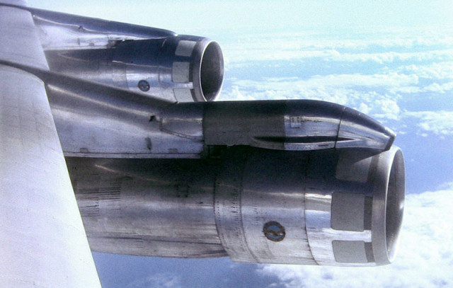
A typical high-bypass ratio turbofan is the Pratt & Whitney JT-9D engine, shown below on the famous Boeing 747. Notice the cowling has a step about 1/2 way back. This is the cold air nozzle where the unheated bypass air exits. The smaller concentric cowling houses the jet engine and the truncated cone at the rear forms the hot-section nozzle. This picture was taken as we approached Sydney, Australia.
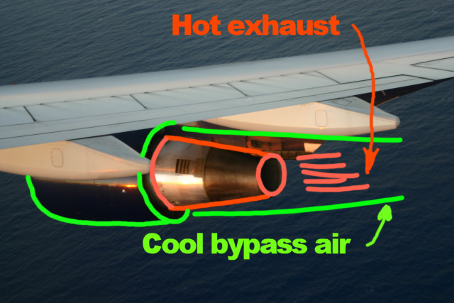
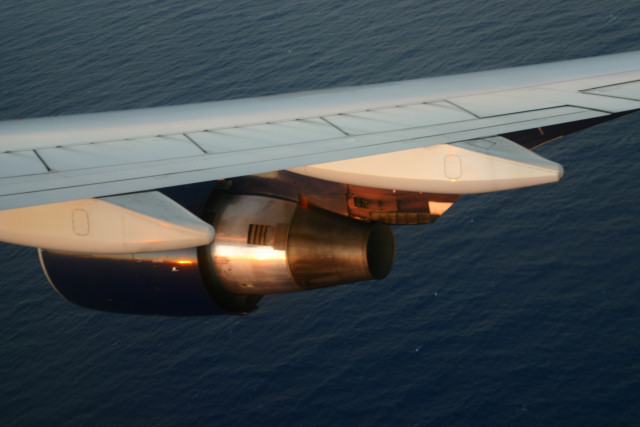
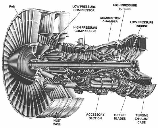
The photo on the left is annotated with a green outline to show the bypass cowling and the cold air exit path, and a red outline to show the turbojet cowling and the hot exhaust exit path. The engine cutaway drawing on the right shows the relative size difference between the large fan diameter and the smaller turbojet diameter.

Now for turboprops: A good example of gear-coupled turboprop engines are the Allison engines installed on the venerable C-130 Hercules, pictured above. This aircraft has 4-bladed propellers that are coupled to the jet engine via a fairly complex gear mechanism. If you've ever been around one of these aircraft when the engines are started, you'll imediately notice the extremely loud and high-pitched noise that each engine produces (be sure to wear earplugs!). Note the vapor contrails coming from the propeller tips in the picture.

Finally, the Pratt & Whitney PT-6 installed on the Beechcraft King Air, shown in the photo above, is a good example of the gas-coupled turbine engine / propeller combination. Notice the position of the propeller blades in this photo (the engines are stopped). The blades are streamlined with the airflow (feathered) as a result of the engine shutdown procedure, performed when the engines were last shutdown. The pilot purposely feathers the propeller blades to increase drag so that the propeller blades can be stopped while the turbine engine is in the final stages of spinning down. Also notice the large exhaust nozzle aimed backwards... This will produce a little bit of extra thrust in flight.
For still more information, see the Wiki entries for turbofan engines, turbojet engines, and turboprop engines..
Click here to go back to the Physics for Future Presidents page.
ALL CONTENT ©EDWARD DUMAS. USE WITHOUT PERMISSION PROHIBITED!"